顯示具有 stm32f4discovery 標籤的文章。 顯示所有文章

2013年4月22日 星期一

作業系統之前的程式 for stm32f4discovery (3) - usart

the 1st 2013422 (1)
the 2nd 20160922

經過 3 年, 我終於知道有哪些還沒搞懂, 趕緊補上。

fig 1

fig 2
fig 3
fig 4
fig 5
選用 usart2 可以使用哪些 pin 呢? 參閱 fig 2 可以使用 PA2 (TX), PA3 (RX), PD5(TX), PD6 (RX) 也可以。PA2, PA3 參考 fig 1 是接在 AHB1, 這就是 myur.c L371 為什麼要初始化 AHB1 的原因。而 usart2 參考 fig5 得知要初始化 APB1 (myur.c L374)。

myur.c
367 void init_usart(uint32_t baudrate)
368 {
369  
370  /* GPIOA clock enable */
371  RCC_AHB1PeriphClockCmd(RCC_AHB1Periph_GPIOA, ENABLE); 
372  
373  /* enable peripheral clock for USART2 */
374  RCC_APB1PeriphClockCmd(RCC_APB1Periph_USART2, ENABLE);


TTL 線接法 (fig 6)


版子端           |    TTL 線
PA2 (usart TX)  |    RX (白色)
PA3 (usart RX)  |    TX (綠色)


fig 6

usart 是很重要的輸入/輸出功能, stm32f4discovery 有好幾組 usart, 這範例選用了 usart2 這組, 接腳是 PA2, PA3, 另外的 gnd, 5v 用, 可接可不接。

感謝 JuluOSDev 陳?毅補充:
「VCC 不需要接 但是 GND 需要接的 不接的話叫作 floating 兩邊的電位不見得相同可能會有奇怪現象, GND相接, 共地才會有一個正確的參考電位平面!」


整條線長這樣, fea 提供了這個方法, 減輕了硬體工作負擔, 要一個純軟體開發人員, 去焊一個 uart 出來, 實在有點困難。插上 pc 的 usb 端之後, 當然沒搞定, 還有 usart code 要寫。


45 NT 參加團購購得, 20130406 拿到, 上圖是接腳圖示。

PA2: usart2_tx -> 白色線 (rx)
PA3: usart2_rx -> 綠色線 (tx)

PA2, PA3 定義請參考:  UM1472 User Manual STM32F4DISCOVERY STM32F4 high-performance discovery board 4.11

我為 uart 困擾很久, 不知道怎麼處理, 本想使用 usb cdc, 不過 usb code 實在複雜, 現在有此方案, usart code 也相對容易些, 總算可以在 stm32f4discovery 印東西了。


alternate function register 稍微提一下, 我也不確定是不是這樣, 看不懂 datasheet 的內容。uart2 rx/tx 是 AF7, PA2, PA3 的 2, 3 是屬於 0..7 所以要設定 0x20 (GPIO alternate function low register) 這組暫存器。

Bits 31:0 AFRLy: Alternate function selection for port x bit y (y = 0..7)
These bits are written by software to configure alternate function I/Os
AFRLy selection:
0000: AF0
0001: AF1
0010: AF2
0011: AF3
0100: AF4
0101: AF5
0110: AF6
0111: AF7
1000: AF8
1001: AF9
1010: AF10
1011: AF11
1100: AF12
1101: AF13
1110: AF14
1111: AF15

AF7 的值是 0111, 也就是 0x7, 所以設定 GPIO alternate function low register。
PA2: 8-11 為 0x7
PA3: 12-15 為 0x7

就是 GPIO_PinAFConfig() 做的設定。

除此之外 source code 沒什麼好介紹的, 從 fea 的版本小改而來 (另外參考網路上抓的 ur 程式碼), 使用 polling mode, 再從 st library 複製/貼上。這程式的價值在於, 我縮到只有一個 .c 檔, 方便對照 datasheet 查閱, 不用和整個 library 奮戰。

source code:
https://github.com/descent/stm32f4_prog
myur.c

make myur.bin

這系列暫時先這樣, 有了基本的 uart 輸入/輸出, 又有了 led, 應該有足夠的武器開工了。

20130425 補充:

由於我的無知, 這個 ur 程式有一個致命的缺點, 我沒有設定 cpu 的工作時脈, 所以 cpu 運作在 16000000 下, 而當我將 cpu 時脈設為 168000000 時, 此 ur 程式無法正常工作, 除錯中 ...

不介意這點的話, 勉強可用。

20130510 補充:
This version can work on 168M HZ cpu clock.
source code:
https://github.com/descent/stm32f4_prog/tree/master/myur_168M

2013年4月16日 星期二

作業系統之前的程式 for stm32f4discovery (2) - 點亮 led, c version

the 1st edition: 20130416 (2)
the 2nd edition: 20160922

toolchain 的使用已經不在困擾我, 困難的是 cpu arm 架構與硬體平台, 這可要看不少資料。通過開發環境的試鍊後, 我打算點亮 led 燈來做為第一個 c 語言的練習程式。

fig 1 http://www.st.com/resource/en/schematic_pack/stm32f4discovery_sch.zip MB997.pdf

不過沒想到這支作業系統之前的程式一開始就難倒我, 難點在於 io 的部份, 不像前一個程式, 這個程式會用到平台相關的程式碼, 點亮 led, 得先要查詢接腳資料, 而查詢接腳資料是很磨人的, 我從這裡的範例程式修改而來。這是 st 公司提供的 library, 可以省下不少看 datasheet 的功夫, 也可幫助程式 port 到其他 st 平台, 是很重要的參考資料。經過三年後 (20160922), 我終於知道要從 fig 1 的文件來得知這個資訊, 這是為什麼要針對 PD12 ~ 15 來設定的原因。

fig 2


而透過 fig 2 得知到初始化 AHB1 mygpio_led.c L253, 因為 GPIO 接腳就接在這個 bus 上。

一樣化繁為簡, 將程式庫的部份抽取出來, 簡化成一個小的作業系統之前的程式。
  2 #include "stm32f4xx_gpio.h"
  3 #include "stm32f4xx.h" 
stm32f4xx_gpio.h, stm32f4xx.h, 從範例程式裡頭挖出來小改一下, 我已經把需要的相關程式碼
抽取出來放在 mygpio_led.c, 只有 stm32.h 和 mygpio_led.c, stm32.ld, 但不要以為這隻程式就很容易看, 得需要查閱 datasheet, 找出相關的暫存器設定方法。

大部份是 gpio, rcc 的 macro。stm32.h 是 coretex-m3 之 stm32 嵌入式系統設計的範例。由於沒有 SDRAM 控制器, 省下這部份的程式碼, lucky!!

stm32.h
 1 #ifndef STM32_H
 2 #define STM32_H
 3 #define GPIOB_CRL     (*(volatile unsigned long *)0x40010c00)
 4 #define GPIOB_BSRR    (*(volatile unsigned long *)0x40010c10)
 5 #define GPIOB_BRR     (*(volatile unsigned long *)0x40010c14)
 6 #define RCC_APB2ENR   (*(volatile unsigned long *)0x40021018)
 7 #define STACK_SIZE 64
 8 extern unsigned long _etext;
 9 extern unsigned long _data;
10 extern unsigned long _edata;
11 extern unsigned long _bss;
12 extern unsigned long _ebss;
13 
14 void ResetISR(void)
15 {
16   unsigned long *pulSrc, *pulDest;
17 
18   pulSrc = &_etext;
19   for (pulDest = &_data; pulDest < &_edata;)
20     *pulDest++ = *pulSrc++;
21   for (pulDest = &_bss; pulDest < &_ebss;)
22     *pulDest++ = 0;
23 
24   main();
25 }
26 
27 typedef void (*pfnISR)(void);
28 __attribute__((section(".stackares")))
29 static unsigned long pulStack[STACK_SIZE];
30 
31 
32 __attribute__((section(".isr_vector")))
33 pfnISR VectorTable[]=
34 {
35   (pfnISR)((unsigned long)pulStack+sizeof(pulStack)),
36   ResetISR
37 };
38 
39 #endif

mygpio_led.c
  1 #include "stm32.h"
  2 
  3 #define RCC_AHB1Periph_GPIOA             ((uint32_t)0x00000001)
  4 #define RCC_AHB1Periph_GPIOB             ((uint32_t)0x00000002)
  5 #define RCC_AHB1Periph_GPIOC             ((uint32_t)0x00000004)
  6 #define RCC_AHB1Periph_GPIOD             ((uint32_t)0x00000008)
  7 #define RCC_AHB1Periph_GPIOE             ((uint32_t)0x00000010)
  8 #define RCC_AHB1Periph_GPIOF             ((uint32_t)0x00000020)
  9 #define RCC_AHB1Periph_GPIOG             ((uint32_t)0x00000040)
 10 #define RCC_AHB1Periph_GPIOH             ((uint32_t)0x00000080)
 11 #define RCC_AHB1Periph_GPIOI             ((uint32_t)0x00000100)
 12 
 13 #define PERIPH_BASE    ((uint32_t)0x40000000) /*!< Peripheral base address in the alias region */
 14 #define AHB1PERIPH_BASE       (PERIPH_BASE + 0x00020000)
 15 #define RCC_BASE              (AHB1PERIPH_BASE + 0x3800)
 16 #define RCC                 ((RCC_TypeDef *) RCC_BASE)
 17 
 18 #define GPIOD_BASE            (AHB1PERIPH_BASE + 0x0C00)
 19 #define GPIOD               ((GPIO_TypeDef *) GPIOD_BASE)
 20 
 21 #define GPIO_OSPEEDER_OSPEEDR0               ((uint32_t)0x00000003)
 22 #define GPIO_OTYPER_OT_0                     ((uint32_t)0x00000001)
 23 #define GPIO_PUPDR_PUPDR0                    ((uint32_t)0x00000003)
 24 
 25 typedef signed int int32_t;
 26 typedef signed short int int16_t;
 27 typedef signed char int8_t;
 28 
 29 typedef unsigned int uint32_t;
 30 typedef unsigned short int uint16_t;
 31 typedef unsigned char uint8_t;
 32 #define     __IO    volatile 
 33 typedef struct
 34 {
 35   __IO uint32_t CR;            /*!< RCC clock control register, Address offset: 0x00 */
 36   __IO uint32_t PLLCFGR;       /*!< RCC PLL configuration register, Address offset: 0x04 */
 37   __IO uint32_t CFGR;          /*!< RCC clock configuration register, Address offset: 0x08 */
 38   __IO uint32_t CIR;           /*!< RCC clock interrupt register, Address offset: 0x0C */
 39   __IO uint32_t AHB1RSTR;      /*!< RCC AHB1 peripheral reset register, Address offset: 0x10 */
 40   __IO uint32_t AHB2RSTR;      /*!< RCC AHB2 peripheral reset register, Address offset: 0x14 */
 41   __IO uint32_t AHB3RSTR;      /*!< RCC AHB3 peripheral reset register, Address offset: 0x18 */
 42   uint32_t      RESERVED0;     /*!< Reserved, 0x1C                                                                    */
 43   __IO uint32_t APB1RSTR;      /*!< RCC APB1 peripheral reset register, Address offset: 0x20 */
 44   __IO uint32_t APB2RSTR;      /*!< RCC APB2 peripheral reset register, Address offset: 0x24 */
 45   uint32_t      RESERVED1[2];  /*!< Reserved, 0x28-0x2C                                                               */
 46   __IO uint32_t AHB1ENR;       /*!< RCC AHB1 peripheral clock register, Address offset: 0x30 */
 47   __IO uint32_t AHB2ENR;       /*!< RCC AHB2 peripheral clock register, Address offset: 0x34 */
 48   __IO uint32_t AHB3ENR;       /*!< RCC AHB3 peripheral clock register, Address offset: 0x38 */
 49   uint32_t      RESERVED2;     /*!< Reserved, 0x3C                                                                    */
 50   __IO uint32_t APB1ENR;       /*!< RCC APB1 peripheral clock enable register, Address offset: 0x40 */
 51   __IO uint32_t APB2ENR;       /*!< RCC APB2 peripheral clock enable register, Address offset: 0x44 */
 52   uint32_t      RESERVED3[2];  /*!< Reserved, 0x48-0x4C                                                               */
 53   __IO uint32_t AHB1LPENR;     /*!< RCC AHB1 peripheral clock enable in low power mode register, Address offset: 0x50 */
 54   __IO uint32_t AHB2LPENR;     /*!< RCC AHB2 peripheral clock enable in low power mode register, Address offset: 0x54 */
 55   __IO uint32_t AHB3LPENR;     /*!< RCC AHB3 peripheral clock enable in low power mode register, Address offset: 0x58 */
 56   uint32_t      RESERVED4;     /*!< Reserved, 0x5C                                                                    */
 57   __IO uint32_t APB1LPENR;     /*!< RCC APB1 peripheral clock enable in low power mode register, Address offset: 0x60 */
 58   __IO uint32_t APB2LPENR;     /*!< RCC APB2 peripheral clock enable in low power mode register, Address offset: 0x64 */
 59   uint32_t      RESERVED5[2];  /*!< Reserved, 0x68-0x6C                                                               */
 60   __IO uint32_t BDCR;          /*!< RCC Backup domain control register,                          Address offset: 0x70 */
 61   __IO uint32_t CSR;           /*!< RCC clock control & status register,                         Address offset: 0x74 */
 62   uint32_t      RESERVED6[2];  /*!< Reserved, 0x78-0x7C                                                               */
 63   __IO uint32_t SSCGR;         /*!< RCC spread spectrum clock generation register,               Address offset: 0x80 */
 64   __IO uint32_t PLLI2SCFGR;    /*!< RCC PLLI2S configuration register,                           Address offset: 0x84 */
 65 } RCC_TypeDef;
 66 
 67 
 68 typedef struct
 69 {
 70   __IO uint32_t MODER;    /*!< GPIO port mode register,               Address offset: 0x00      */
 71   __IO uint32_t OTYPER;   /*!< GPIO port output type register,        Address offset: 0x04      */
 72   __IO uint32_t OSPEEDR;  /*!< GPIO port output speed register,       Address offset: 0x08      */
 73   __IO uint32_t PUPDR;    /*!< GPIO port pull-up/pull-down register,  Address offset: 0x0C      */
 74   __IO uint32_t IDR;      /*!< GPIO port input data register,         Address offset: 0x10      */
 75   __IO uint32_t ODR;      /*!< GPIO port output data register,        Address offset: 0x14      */
 76   __IO uint16_t BSRRL;    /*!< GPIO port bit set/reset low register,  Address offset: 0x18      */
 77   __IO uint16_t BSRRH;    /*!< GPIO port bit set/reset high register, Address offset: 0x1A      */
 78   __IO uint32_t LCKR;     /*!< GPIO port configuration lock register, Address offset: 0x1C      */
 79   __IO uint32_t AFR[2];   /*!< GPIO alternate function registers,     Address offset: 0x20-0x24 */
 80 } GPIO_TypeDef;
 81 
 82 #define GPIO_MODER_MODER0                    ((uint32_t)0x00000003)
 83 
 84 typedef enum {DISABLE = 0, ENABLE = !DISABLE} FunctionalState;
 85 
 86 typedef enum
 87 { 
 88   GPIO_OType_PP = 0x00,
 89   GPIO_OType_OD = 0x01
 90 }GPIOOType_TypeDef;
 91 
 92 typedef enum
 93 { 
 94   GPIO_PuPd_NOPULL = 0x00,
 95   GPIO_PuPd_UP     = 0x01,
 96   GPIO_PuPd_DOWN   = 0x02
 97 }GPIOPuPd_TypeDef;
 98 
 99 typedef enum
100 { 
101   GPIO_Mode_IN   = 0x00, /*!< GPIO Input Mode */
102   GPIO_Mode_OUT  = 0x01, /*!< GPIO Output Mode */
103   GPIO_Mode_AF   = 0x02, /*!< GPIO Alternate function Mode */
104   GPIO_Mode_AN   = 0x03  /*!< GPIO Analog Mode */
105 }GPIOMode_TypeDef;
106 
107 typedef enum
108 { 
109   GPIO_Speed_2MHz   = 0x00, /*!< Low speed */
110   GPIO_Speed_25MHz  = 0x01, /*!< Medium speed */
111   GPIO_Speed_50MHz  = 0x02, /*!< Fast speed */
112   GPIO_Speed_100MHz = 0x03  /*!< High speed on 30 pF (80 MHz Output max speed on 15 pF) */
113 }GPIOSpeed_TypeDef;
114 
115 #define GPIO_Pin_0                 ((uint16_t)0x0001)  /* Pin 0 selected */
116 #define GPIO_Pin_1                 ((uint16_t)0x0002)  /* Pin 1 selected */
117 #define GPIO_Pin_2                 ((uint16_t)0x0004)  /* Pin 2 selected */
118 #define GPIO_Pin_3                 ((uint16_t)0x0008)  /* Pin 3 selected */
119 #define GPIO_Pin_4                 ((uint16_t)0x0010)  /* Pin 4 selected */
120 #define GPIO_Pin_5                 ((uint16_t)0x0020)  /* Pin 5 selected */
121 #define GPIO_Pin_6                 ((uint16_t)0x0040)  /* Pin 6 selected */
122 #define GPIO_Pin_7                 ((uint16_t)0x0080)  /* Pin 7 selected */
123 #define GPIO_Pin_8                 ((uint16_t)0x0100)  /* Pin 8 selected */
124 #define GPIO_Pin_9                 ((uint16_t)0x0200)  /* Pin 9 selected */
125 #define GPIO_Pin_10                ((uint16_t)0x0400)  /* Pin 10 selected */
126 #define GPIO_Pin_11                ((uint16_t)0x0800)  /* Pin 11 selected */
127 #define GPIO_Pin_12                ((uint16_t)0x1000)  /* Pin 12 selected */
128 #define GPIO_Pin_13                ((uint16_t)0x2000)  /* Pin 13 selected */
129 #define GPIO_Pin_14                ((uint16_t)0x4000)  /* Pin 14 selected */
130 #define GPIO_Pin_15                ((uint16_t)0x8000)  /* Pin 15 selected */
131 #define GPIO_Pin_All               ((uint16_t)0xFFFF)  /* All pins selected */
132 
133 typedef struct
134 {
135   uint32_t GPIO_Pin;              /*!< Specifies the GPIO pins to be configured.
136                                        This parameter can be any value of @ref GPIO_pins_define */
137 
138   GPIOMode_TypeDef GPIO_Mode;     /*!< Specifies the operating mode for the selected pins.
139                                        This parameter can be a value of @ref GPIOMode_TypeDef */
140 
141   GPIOSpeed_TypeDef GPIO_Speed;   /*!< Specifies the speed for the selected pins.
142                                        This parameter can be a value of @ref GPIOSpeed_TypeDef */
143 
144   GPIOOType_TypeDef GPIO_OType;   /*!< Specifies the operating output type for the selected pins.
145                                        This parameter can be a value of @ref GPIOOType_TypeDef */
146 
147   GPIOPuPd_TypeDef GPIO_PuPd;     /*!< Specifies the operating Pull-up/Pull down for the selected pins.
148                                        This parameter can be a value of @ref GPIOPuPd_TypeDef */
149 }GPIO_InitTypeDef;
150 
151 void Delay(uint32_t delay )
152 {
153   while(delay) delay--;
154 }
155 
156 void RCC_AHB1PeriphClockCmd(uint32_t RCC_AHB1Periph, FunctionalState NewState)
157 { 
158   /* Check the parameters */
159   //assert_param(IS_RCC_AHB1_CLOCK_PERIPH(RCC_AHB1Periph));
160   
161   //assert_param(IS_FUNCTIONAL_STATE(NewState));
162   if (NewState != DISABLE)
163   {
164     RCC->AHB1ENR |= RCC_AHB1Periph;
165   } 
166   else
167   { 
168     RCC->AHB1ENR &= ~RCC_AHB1Periph;
169   }
170 }  
171 
172 #define RCC_AHB1Periph_GPIOD             ((uint32_t)0x00000008)
173 
174 
175 void GPIO_Init(GPIO_TypeDef* GPIOx, GPIO_InitTypeDef* GPIO_InitStruct)
176 {
177   uint32_t pinpos = 0x00, pos = 0x00 , currentpin = 0x00;
178 
179 #if 0
180   /* Check the parameters */
181   assert_param(IS_GPIO_ALL_PERIPH(GPIOx));
182   assert_param(IS_GPIO_PIN(GPIO_InitStruct->GPIO_Pin));
183   assert_param(IS_GPIO_MODE(GPIO_InitStruct->GPIO_Mode));
184   assert_param(IS_GPIO_PUPD(GPIO_InitStruct->GPIO_PuPd));
185 #endif
186   /* -------------------------Configure the port pins---------------- */
187   /*-- GPIO Mode Configuration --*/
188   for (pinpos = 0x00; pinpos < 0x10; pinpos++)
189   {
190     pos = ((uint32_t)0x01) << pinpos;
191     /* Get the port pins position */
192     currentpin = (GPIO_InitStruct->GPIO_Pin) & pos;
193 
194     if (currentpin == pos)
195     {
196       GPIOx->MODER  &= ~(GPIO_MODER_MODER0 << (pinpos * 2));
197       GPIOx->MODER |= (((uint32_t)GPIO_InitStruct->GPIO_Mode) << (pinpos * 2));
198 
199       if ((GPIO_InitStruct->GPIO_Mode == GPIO_Mode_OUT) || (GPIO_InitStruct->GPIO_Mode == GPIO_Mode_AF))
200       {
201         /* Check Speed mode parameters */
202         //assert_param(IS_GPIO_SPEED(GPIO_InitStruct->GPIO_Speed));
203 
204         /* Speed mode configuration */
205         GPIOx->OSPEEDR &= ~(GPIO_OSPEEDER_OSPEEDR0 << (pinpos * 2));
206         GPIOx->OSPEEDR |= ((uint32_t)(GPIO_InitStruct->GPIO_Speed) << (pinpos * 2));
207 
208         /* Check Output mode parameters */
209         //assert_param(IS_GPIO_OTYPE(GPIO_InitStruct->GPIO_OType));
210 
211         /* Output mode configuration*/
212         GPIOx->OTYPER  &= ~((GPIO_OTYPER_OT_0) << ((uint16_t)pinpos)) ;
213         GPIOx->OTYPER |= (uint16_t)(((uint16_t)GPIO_InitStruct->GPIO_OType) << ((uint16_t)pinpos));
214       }
215 
216       /* Pull-up Pull down resistor configuration*/
217       GPIOx->PUPDR &= ~(GPIO_PUPDR_PUPDR0 << ((uint16_t)pinpos * 2));
218       GPIOx->PUPDR |= (((uint32_t)GPIO_InitStruct->GPIO_PuPd) << (pinpos * 2));
219     }
220   }
221 }
222 
223 void GPIO_SetBits(GPIO_TypeDef* GPIOx, uint16_t GPIO_Pin)
224 {   
225   /* Check the parameters */
226   //assert_param(IS_GPIO_ALL_PERIPH(GPIOx));
227   //assert_param(IS_GPIO_PIN(GPIO_Pin));
228     
229   GPIOx->BSRRL = GPIO_Pin;
230 } 
231 
232 
233 void GPIO_ResetBits(GPIO_TypeDef* GPIOx, uint16_t GPIO_Pin)
234 {
235   /* Check the parameters */
236   //assert_param(IS_GPIO_ALL_PERIPH(GPIOx));
237   //assert_param(IS_GPIO_PIN(GPIO_Pin));
238 
239   GPIOx->BSRRH = GPIO_Pin;
240 }
241 
242 int main(void)
243 {
244     //init_led();
245     GPIO_InitTypeDef GPIO_InitStructure;
246     
247     #if 0
248     /* Enable GPIO C clock. */
249     RCC_APB2PeriphClockCmd(RCC_APB2Periph_GPIOC, ENABLE);
250     #endif
251 
252     /* GPIOD Periph clock enable */
253     RCC_AHB1PeriphClockCmd(RCC_AHB1Periph_GPIOD, ENABLE);
254 
255   /* Configure PD12, PD13, PD14 and PD15 in output pushpull mode */
256   GPIO_InitStructure.GPIO_Pin = GPIO_Pin_11 | GPIO_Pin_12 | GPIO_Pin_13| GPIO_Pin_14| GPIO_Pin_15;
257   GPIO_InitStructure.GPIO_Mode = GPIO_Mode_OUT;
258   GPIO_InitStructure.GPIO_OType = GPIO_OType_PP;
259   GPIO_InitStructure.GPIO_Speed = GPIO_Speed_100MHz;
260   GPIO_InitStructure.GPIO_PuPd = GPIO_PuPd_NOPULL;
261   GPIO_Init(GPIOD, &GPIO_InitStructure);
262 
263       
264   while (1)
265   {     
266     /* PD12 to be toggled, green */
267     GPIO_SetBits(GPIOD, GPIO_Pin_12);
268     GPIO_SetBits(GPIOD, GPIO_Pin_11);
269         
270     /* Insert delay */ 
271     Delay(0x3FFFFF);
272 
273 #if 1
274     /* PD13 to be toggled, orange */
275     GPIO_SetBits(GPIOD, GPIO_Pin_13);
276 
277     /* Insert delay */
278     Delay(0x3FFFFF);
279 #endif    
280     /* PD14 to be toggled, ref */
281     GPIO_SetBits(GPIOD, GPIO_Pin_14);
282       
283     /* Insert delay */
284     Delay(0x3FFFFF);
285 #if 1
286     /* PD15 to be toggled, blue */
287     GPIO_SetBits(GPIOD, GPIO_Pin_15);
288     /* Insert delay */
289     Delay(0x5FFFFF);
290 #endif
291     GPIO_ResetBits(GPIOD, GPIO_Pin_11 | GPIO_Pin_12|GPIO_Pin_13|GPIO_Pin_14|GPIO_Pin_15);
292 
293     /* Insert delay */
294     Delay(0x6FFFFF);
295   }
296 
297 
320 }

stm32.ld
 1 MEMORY
 2 {
 3   FLASH (rx) : ORIGIN = 0x00000000, LENGTH = 1024K
 4   SRAM (rwx) : ORIGIN = 0x20000000, LENGTH = 192K
 5 }
 6 
 7 SECTIONS
 8 {
 9   .text :
10   {
11     KEEP(*(.isr_vector .isr_vector.*))
12     *(.text .text.*)
13     *(.rodata .rodata*)
14     _etext = .;
15   } > FLASH
16   .data : AT (_etext)
17   {
18     _data = .;
19     *(.data .data.*)
20     _edata = .;
21   } > SRAM
22   .bss(NOLOAD) :
23   {
24     _bss = .;
25     *(.bss .bss.*)
26     *(COMMON)
27     . = ALIGN(4);
28     _ebss = .;
29   } > SRAM
30   .stackarea(NOLOAD) :
31   {
32     . = ALIGN(8);
33     *(.stackarea .stackares.*)
34     . = ALIGN(8);
35   }
36   . = ALIGN(4);
37   _end = .;
38 }

程式結果就是先閃綠燈, 閃紅燈在一起熄滅, 如此循環下去。


fig 3 使用 saleae logic 16 抓取 30 秒
而在 20160814 買了 saleae logic 16 之後, 我就可以測量 GPIO 訊號, 請參考 fig 3 的接法,  ch1 接在 PD12, ch2 接在 PD13。

fig 4 rx1 (ch1) 是 PD12 - green led
fig 4 sync (ch2) 是 PD 13 - orange led

再參考 fig 4, 當 rx1, sync 一起降下來的時候, 就是同時暗掉, 升上去時就是亮燈。

也可以得知 Delay(0x3FFFFF); 大概是 4 秒左右, 在這時候的我還沒有可以正確設定 timer 的能力, 不過現在我知道要怎麼設定了。

fig 4 使用 saleae logic 16 抓取 30 秒

我要解說的部份只和開機程式有關, IO 部份請自己搞定, 這不是文章的重點。和 x86 不同, cortex-m3 可以「完全」使用 c 語言來寫開機程式, 而不像 x86 需要 inline 組合語言。一開機, 位址 0~3 存放的值會被填到 sp, 完成 stack 設定, 在 c 語言中完成最重要的設定。

再來是 bss section:

stm32.h
13 void ResetISR(void)
14 {
15   unsigned long *pulSrc, *pulDest;
16 
17   pulSrc = &_etext;
18   for (pulDest = &_data; pulDest < &_edata;)
19     *pulDest++ = *pulSrc++;
20   for (pulDest = &_bss; pulDest < &_ebss;)
21     *pulDest++ = 0;
22 
23   main();
24 }

這段 code 便是在初使化 .bss, .data, 就這樣完成 c startup code, 完全不需要組合語言介入, 厲害的設計。

也許你想知道 .bss, .data 為什麼要初始化, 這不是很容易寫在 blog 上, 用個例子簡單說明:

int a=6;
void func()
{
  static int i;
}

a 位於 .data, i 位於 .bss, 在程式執行時, a 要是 6, 而 i 要是 0, 這不是憑空得來的, 初始化 .bss, .data 就是在完成這樣的工作, 我知道, 這只能解除你一半的疑惑, 你一定想知道更多吧!

那 x86 的 bss section 也可以這樣寫嗎?由於有名的 segment address, 你得先確定你指的位址 0x100 真的是絕對位址 0x100 嗎?這是很容易搞亂的。

而透過 link script, section(".isr_vector") 會被放到 0 開頭的位址, 達到 0~3 是 stack value, 4 ~ 7 是 reset handle 的目的, 進而透過 ResetISR call main 去執行 main()。

簡單的 gpio led 程式並沒有想像中簡單吧, 所以像是 arduino 之類的開發版將這些困難都隱藏起來是花了不少苦心, 不過我的學習方式正是要把隱藏在冰山下的真像挖出來, 這也是為什麼又過了三年, 還是只在 gpio led 打轉。

按照之前的慣例, 下一個應該是 c++ 的版本, 不過 ...

source code:
https://github.com/descent/stm32f4_prog/tree/master/led

補充 stm32 p103 模擬器中的初始化程式碼:

stm32_p103_demos/libraries/CMSIS/CM3/DeviceSupport/ST/STM32F10x/startup/gcc_ride7/startup_stm32f10x_md.s

 1     .section .text.Reset_Handler
 2  .weak Reset_Handler
 3  .type Reset_Handler, %function
 4 Reset_Handler: 
 5 
 6 /* Copy the data segment initializers from flash to SRAM */  
 7   movs r1, #0
 8   b LoopCopyDataInit
 9 
10 CopyDataInit:
11  ldr r3, =_sidata
12  ldr r3, [r3, r1]
13  str r3, [r0, r1]
14  adds r1, r1, #4
15     
16 LoopCopyDataInit:
17  ldr r0, =_sdata
18  ldr r3, =_edata
19  adds r2, r0, r1
20  cmp r2, r3
21  bcc CopyDataInit
22  ldr r2, =_sbss
23  b LoopFillZerobss
24 /* Zero fill the bss segment. */  
25 FillZerobss:
26  movs r3, #0
27  str r3, [r2], #4
28     
29 LoopFillZerobss:
30  ldr r3, = _ebss
31  cmp r2, r3
32  bcc FillZerobss
33 /* Call the clock system intitialization function.*/
34   bl  SystemInit  
35 /* Call the application's entry point.*/
36  bl main
37  bx lr    
38 .size Reset_Handler, .-Reset_Handler
L36 會 call main

ref:
gpio gpio push-pull or open drain:

介紹一些 arm 指令:
http://jnotes.googlecode.com/svn-history/r105/trunk/Notes/NotesOnCM3/stm32WithGCC.html

books: coretex-m3 之 stm32 嵌入式系統設計

2013年4月10日 星期三

作業系統之前的程式 for stm32f4 - discovery (1) - 1 加到 10 , asm version

對 x86 的學習暫時告個段落, 我開始邁向另一個硬體平台 arm (cortex-m), 使用的是 stm32f4discovery 這塊開發板, 比較不滿意的是沒有 mmu, 192k ram 也實在小了點, 咦!前一篇提過了阿?那我就再說一次。至少給我 1M 阿!我實在是不習慣 mcu 的小資源。

重複同樣的學習方式, 先來開發第一支作業系統之前的程式, 和 x86 pc 有 bios 不同, 這支程式就是板子開機後第一支執行的程式。比起作業系統之前的程式, 標題取為開機後的第一支程式聽起來似乎威一點, 但是對稱之美是很重要的, 所以就這樣囉!

和之前一樣, 先來個組合語言的版本, 而和 x86 一樣, 有不同的組合語言語法 - arm/gnu, 這裡的例子是 gnu arm 組合語言語法。這是 ARM Cortex-M3 嵌入式系統 設計入門 page 19-3 的範例 - 1 加到 10。

one2ten.S
 1 # ARM Cortex-M3 嵌入式系統 設計入門 p 19-3 
 2 .equ STACK_TOP, 0x20000800
 3 .text
 4 .global _start
 5 .code 16
 6 .syntax unified
 7 _start:
 8   .word STACK_TOP, start
 9   .type start, function 
10   # let lsb to 1
11 
12 start:
13   movs r0, #10
14   movs r1, #0
15 
16 loop:
17   adds r1, r0
18   subs r0, #1
19   bne loop
20 
21 deadloop:
22   b deadloop
23 .end

編譯指令在作業系統之前的程式是很重要的, 一定要列出來:
arm-none-eabi-as -g -mcpu=cortex-m3 -mthumb -o factorial.o factorial.S
arm-none-eabi-ld -Ttext 0x0 -o factorial.elf factorial.o
arm-none-eabi-objcopy -O binary factorial.elf factorial.bin

對於我們的第一支 cortex-m3 程式, 就簡單點, 不用 link script。

再來和 x86 pc 有點不同, 把這程式燒錄到 flash (pc 則是複製到軟碟或是硬碟), 無法使用平常的 cp/dd 指令, 得用 openocd/stlink。

flash address: 0x8000000
使用 stlink 的指令 st-flash 來把程式寫入到 flash。

st-flash write factorial.bin 0x8000000

openocd 指令請參考:
Programming STM32 F2, F4 ARMs under Linux: A Tutorial from Scratch

開機後在預設情形下, flash address 會被 map 到 0x0 上, 所以可以簡單看成從位址 0 的地方開始執行程式。

由於沒有使用特定開發板的 IO, 所以應該可以在各家的 cortex-m 系列 的開發板執行, 也可以用〖作業系統之前的程式 for stm32f4discovery (0)〗提到的模擬器來執行。

和 arm v6 以前的架構有點不同, 找書籍/資料時可別看到 arm 就認為是自己要看的資料。arm 開始幹不相容的事情了, 沒有 intel 的老舊包袱還真好。

讓 stm32f4discovery 一開機就執行的程式要怎麼寫呢?
L8, L9 就是重點:
  • L8 的 .word 填上兩個 4 個 byte 值, 第一個就是 stack (sp) 的位址, 所以填上什麼數字, stack 位址就從那開始。開機時, cortex-m3 系列會把 0~3 這 4 byte 的值填到 sp。
  • L8 的 start 則是一開機就會跳到該位址執行程式碼, 本範例是 start 的位址, 所以一開機之後, stack 設好了, 程式也從 start 開始執行。而這 8 個 byte 必須在執行檔的前 8 個 byte。

這是怎麼做到的?
arm-none-eabi-ld -Ttext 0x0 表示將 text section 從 0 開始算起, 所以 .word STACK_TOP, start 這行指令, 就會佔據執行檔的前 8 byte, STACK_TOP 佔了 4 byte, start 也佔了 4 byte。

descent@debianlinux:stm32_prog$ hexdump -C factorial.bin 
00000000  00 08 00 20 09 00 00 00  0a 20 00 21 09 18 01 38  |... ..... .!...8|
00000010  7f f4 fc af ff f7 fe bf 

紅色 20000800 就是 sp 的值, 從 gdb dump register 可以得證。

(gdb) target remote localhost:1234
Remote debugging using localhost:1234
0x00000008 in ?? ()
(gdb) file ./
.factorial.S.swp  factorial.S.html  h.sh              stm32.h
.git/             factorial.bin     hello.c           stm32.ld
.makefile.swp     factorial.elf     makefile          stm32f4xx.h
README.md         factorial.o       mymain.c          stm32f4xx_gpio.h
factorial.S       g1.sh             q.sh              
(gdb) file ./factorial.elf 
A program is being debugged already.
Are you sure you want to change the file? (y or n) y
Reading symbols from /home/descent/git/jserv_course/stm32_prog/factorial.elf...done.
(gdb) l
1 # ARM Cortex-M3 嵌入式系統 設計入門 p 19-3 
2 .equ STACK_TOP, 0x20000800
3 .text
4 .global _start
5 .code 16
6 .syntax unified
7 _start:
8   .word STACK_TOP, start
9   .type start, function 
10   # let lsb to 1
(gdb) l
11 
12 start:
13   movs r0, #10
14   movs r1, #0
15 
16 loop:
17   adds r1, r0
18   subs r0, #1
19   bne loop
20 
(gdb) b 13
Breakpoint 1 at 0xa: file factorial.S, line 13.
(gdb) r
The "remote" target does not support "run".  Try "help target" or "continue".
(gdb) c
Continuing.

Breakpoint 1, start () at factorial.S:14
14   movs r1, #0
(gdb) i r
r0             0xa 10
r1             0x0 0
r2             0x0 0
r3             0x0 0
r4             0x0 0
r5             0x0 0
r6             0x0 0
r7             0x0 0
r8             0x0 0
r9             0x0 0
r10            0x0 0
r11            0x0 0。
r12            0x0 0
sp             0x20000800 0x20000800
lr             0x0 0
pc             0xa 0xa
cpsr           0x173 371
(gdb) 

藍色的 00000009 是 start 的位址, 從 objdump 看來明明就是 00000008, 怎麼多了個 1。這是 thumb 的關係, 若是 00000008 會讓 cpu 以為是在 arm 模式, 會得到一個 Hard Fault Exception。

這就是 L9 的作用, 沒有這行, 這個值就會是 00000008。
 9   .type start, function 

arm-none-eabi-objdump -d factorial.elf
 1 
 2 factorial.elf:     file format elf32-littlearm
 3 
 4 
 5 Disassembly of section .text:
 6 
 7 00000000 <_start>:
 8    0: 20000800  .word 0x20000800
 9    4: 00000009  .word 0x00000009
10 
11 00000008 <start>:
12    8: 200a       movs r0, #10
13    a: 2100       movs r1, #0
14 
15 0000000c <loop>:
16    c: 1809       adds r1, r1, r0
17    e: 3801       subs r0, #1
18   10: f47f affc  bne.w c <loop>
19 
20 00000014 <deadloop>:
21   14: f7ff bffe  b.w 14 <deadloop>

一樣不需要寫 dram controller 的 code, lucky!!因為使用的是 sram, 似乎不用寫什麼程式碼就可直接使用。好了, 解釋完畢, 組合語言的部份請自己查閱, 用 openocd/gdb 來 single step 吧!依照慣例, 應該猜得到, 下一篇會是 c 語言的版本

source code:
https://github.com/descent/stm32f4_prog

ref:
ARM Cortex-M3 嵌入式系統 設計入門

2013年4月5日 星期五

作業系統之前的程式 for stm32f4discovery (0) - 打造 linux 開發環境

Fig 1. stm32f4discovery
the 1st edition: 20130405
the 2nd edition: 20150119
the 3rd edition: 20160913
the 4th edition: 20161221

簡體中文網站:
stm8, stm32 社區
這個系列累積了不少篇幅, 以下是所有系列的文章目錄:
bare-metal for stm32f4 discovery board content

《作業系統之前的程式》這又稱為 bare-metal 程式, 該系列紀錄 x86 os kernel 開發的學習經驗, 我想依樣畫葫蘆拿到 arm 的學習上, 重新學習一個完全不一樣的平台。

這是一個辛苦的開始, 縱使有了 x86 的學習經驗, 也無法帶來太多的助益, 仍然需要閱讀大量的資料, 甚至去找到相關資料也是個難題, 而程式的撰寫也只是最基本的練習。

你看我從 20130405 撰寫這篇文章開始到現在, 還沒開發出這平台的 os kernel 就知道我在偷懶這事情的不易。

但在開始第一個作業系統之前的程式 for stm32f4discovery 之前, 得先來打造開發環境, 這是與 x86 native toolchain 不同的地方, 別小看這部份, 這可不是一件容易的事, 最主要的部份就是 arm toolchain (cross compiler) 和燒錄程式碼到 stm32f4discovery flash 的工具。

目前市面上琳琅滿目的開發板, 要從中挑選實在不容易。Fig 1 是 stm32f4discovery, jserv 的《進階嵌入式系統開發與實作》課程 (201209~201301) 就是使用這塊開發板, 以 700 NT 購得。因為參加了這個課程, 所以才選定這塊開發板, 照著課程的資源來學習, 最是省事。

後來 stm32 出了不少系列有 stm32f429, stm32f7 ...

提供了 non-mmu linux 的支援
選擇板子時會有一個問題, 怎麼把程式碼燒錄到那塊板子上呢? 這是個大問題。而這塊開發板珍貴的地方就是內建 ST-LINK/V2, 可以將程式碼燒錄到 flash, 再也不怕燒爛 flash; 更珍貴的地方是: 還可以使用類似 jtag 的方式 debug, 不用另外買個 jtag, 當然這些都需要搭配的軟體才能運作, openocd 或是 st-util 都可以做到, 這是開發 os 等級程式碼的利器。我知道還有一塊版子也有類似的功能, freescale m0+ 系列, 使用的是 opensda, 不過我不確定 openocd 是不是可以支援 opensda。

而我後來開發了 sd card boot, 可以方便撰寫測試程式, 不一定要寫到 flash, 紀錄在《作業系統之前的程式 for stm32f4discovery (18.3) - 載入並執行 sd card 上的 elf

而 stm32 提供了 bootloader 的方式, 就算沒有 st-link 也可以燒錄程式, 但還要調整 jmp, 不是很方便。有興趣可參考: stm32f4discovery system memory - boot loader

Arduino 或是 Intel Galileo 這種開發版主打快速、簡單、好開發。看看這些書名就可窺探一二:
這些書籍都會有一些很有趣的實作專題, 例如驅動馬達、機器人互動裝置等等 ... 這些很有趣, 能做出來會有一定的成就感。不過我志不在此, 我想研究最底層的秘密, 而不是作組合積木的事情, 例如上電之後怎麼執行第一支程式, 某個 gpio 該怎麼使用? 那個按鈕要能發揮作用需要做什麼事情 ... 所以我會需要有類似 jtag 功能的版子, 這種等級的除錯很難避免, 也很難靠 printf 來除錯, 甚至要自己寫 printf。

不過偶爾看到別人用這些東西做出很好玩的東西, 例如機器手臂、機器人, 自己卻和 datasheet, c/asm code, debugger 打交道, single step 錯誤的程式碼, 而終端機畫面只有一些簡易的文字訊息, 還真是有些落漠之感, 我也想做出一些有趣的裝置。

maker 雜誌中文版》有更多類似這樣的作品, 每一件都很能吸引人。

回到 stm32, stm32f4 mcu 全系列可參考這裡

這是以 ARM Cortex-M4 為核心的開發版。沒有 mmu, 所以不能練習 page mapping, 這是我覺得比較可惜的部份; 但有個記憶體保護單元 (MPU), 可以保護某個記憶體區塊。這塊板子用的是 stm32 的 STM32F407VG, 其基本規格:

時脈: 168 MHz
flash & ram size:
STM32F407VGT6 microcontroller featuring 1 MB of Flash memory, 192 KB of RAM in an LQFP100 package.

以下的連結可以下載 firmware, 方便寫程式, 不用辛苦的對付暫存器。

Related Tools and Software
Part Number Description
STM-STUDIO STM Studio run-time variables monitoring and visualization tool for STM8 and STM32 microcontrollers
STM32CubeF4 Embedded software for STM32 F4 series (HAL low level drivers, USB, TCP/IP, File system, RTOS, Graphic - coming with examples running on ST boards)
STSW-STM32068 STM32F4DISCOVERY board firmware package, including 22 examples (covering USB Host, audio, MEMS accelerometer and microphone) (AN3983)
STSW-STM32142 Using STM32F4 MCU power modes with best dynamic efficiency (AN4365)


我還真不習慣只有 192KB 的記憶體。

usb 有兩邊, 插上 CN1 (如 Fig 1 白色 usb 線) 接到 pc 後, 就可看到 led 燈的閃爍效果 (如 Fig 1), 代表這是一塊正常的板子。開發程式, 燒錄程式也都是接在 CN1 上, 這是 ST-LINK/V2 chip 提供的功能。

這塊板子相關的 datasheet 和 sample code: datasheet for stm32f4 discovery

這 3 本的厚度不輸給 intel 那 3 本, 真的很厚, 有得看了。

stm32f4 - discovery 用的是 STM32F407VGT6, 詳細的 mcu 資訊要找這顆的 datasheet。
stm32f407 datasheet: http://www.st.com/st-web-ui/static/active/en/resource/technical/document/reference_manual/DM00031020.pdf

以下連結已經失效:
http://www.st.com/internet/com/TECHNICAL_RESOURCES/TECHNICAL_LITERATURE/REFERENCE_MANUAL/DM00031020.pdf

datasheet 竟然有中文版本, 我嚇傻了!!
http://www.stmcu.org/document/detail/index/id-200614

中文官網:
http://www.stmcu.org/

除了開發環境之外, 文件的閱讀/尋找也是一個難題, 並不是只讀 stm32f407 datasheet 這份就足夠。

AN2606 Application note 提到 system memory 的 bootloader。
UM0462 在介紹 flash loader demonstrator 的用法。
AN3155 Application note 介紹 USART protocol used in the STM32 bootloader。

除了 stm32 提供的文件, arm 原廠的文件要讀嗎? 這份 ARM®v7-M Architecture Reference Manual 要讀嗎? 你可以只看官方的 datasheet 就能開發程式了嗎? 也許你可以, 但是我不行, 所以我還買了這些書籍

用原廠準備的環境 (on ms windows), STM 沒提供自己的開發工具, 請參考: What should I use to develop on STM32? stm 有支援這些開發工具, 一定可以減輕開發環境的先前準備工作, 而 free 的版本幾乎都會有些限制, 例如執行檔大小不能超過 32K, 其實好像也不太容易超過這限制。而我習慣 linux vi + makefile 的工作環境, 打造這樣的開發環境並不算輕鬆, 否則也不會特地 blog 一篇, 來照著課程自虐吧!

在 linux 上的開發方式:


toolchain & qemu stm32 模擬器: http://wiki.csie.ncku.edu.tw/embedded/Lab1

如果你喜歡從原始碼建立編譯器工具組的話可以參考以下連結, toolchain build from source:
  1. https://github.com/jsnyder/arm-eabi-toolchain (fb 顏 sir 提供)
  2. http://cu.rious.org/make/compiling-the-arm-cortex-m4-toolchain-yourself/
  3. https://github.com/cccc/STM32-Toolchain (gcc-4.8.0)
  4. STM32F4 – Build Your Own GNU ARM Cross-Toolchain From Scratch (cross compiler gcc 4.9 我使用 gcc 4.7 的版本才建構的出來)
    (cross compiler gcc 5.1 我使用 gcc 4.9/5.2 的版本才建構的出來)

我自己準備了 4.7, 4.8, 4.9.2 (從上述第四個修改而來) 三個版本。


debian 提供了這些 toolchain

root@debianlinux:apt# apt-cache search gcc|grep arm
cpp-aarch64-linux-gnu - GNU C preprocessor (cpp) for architecture arm64
cpp-arm-linux-gnueabi - GNU C preprocessor (cpp) for architecture armel
cpp-arm-linux-gnueabihf - GNU C preprocessor (cpp) for architecture armhf
gcc-aarch64-linux-gnu - GNU C compiler for architecture arm64
gcc-arm-linux-gnueabi - GNU C compiler for architecture armel
gcc-arm-linux-gnueabihf - GNU C compiler for architecture armhf
gfortran-aarch64-linux-gnu - GNU Fortran 95 compiler for architecture arm64
gfortran-arm-linux-gnueabi - GNU Fortran 95 compiler for architecture armel
gfortran-arm-linux-gnueabihf - GNU Fortran 95 compiler for architecture armhf
gcc-arm-none-eabi - GCC cross compiler for ARM Cortex-A/R/M processors

apt-get install gcc-arm-none-eabi

install gdb:
apt-get install gdb-arm-none-eabi

arm-2013.05-23-arm-none-eabi.src.tar.bz2 (上述第一個 url) 這個版本, 需要使用 makeinfo 4.13 (texinfo-4.13.tar.gz) 才可以正確編譯 binutils doc 目錄, 在我的 debian makeinfo 是 5.2 會在編譯 binutils 出問題。目前的版本已經修正這問題。

我會準備一個 script 用來載入 toolchain PATH 環境變數:
env_stm32_gcc-51.softfp
1 export PS1="\[\e[32;1m\][stm32-dev]\[\e[0m\]:\W> "
2 export PATH=/home/descent/work/st_toolchain/arm.softfp/bin:$PATH  

用 . 來載入它
$ . env_stm32_gcc-51.softfp

PS1 的改變會帶來很明顯的提示符號, 知道自己目前是在 cortex m3 的開發環境。

使用 openocd/stlink 來將程式寫到 stm32f4discovery flash (openocd/stlink/serialusb) :
http://wiki.csie.ncku.edu.tw/embedded/Lab6

Bus 002 Device 003: ID 0483:3748 SGS Thomson Microelectronics ST-LINK/V2

編譯與安裝 stlink
sudo apt-get install automake* libtool libusb-1.0-0-dev libgtk-3-dev
apt-get install gdb-multiarch
git clone http://github.com/texane/stlink.git
cd stlink
./autogen.sh
./configure --prefix=/usr --with-gtk
make
sudo make install
sudo cp 49-stlinkv2.rules /etc/udev/rules.d/

若不需要 gui 的版本, 不用加入 --with-gtk option, 也不需要安裝 libgtk-3-dev, 就不會編譯 stlink-gui。

20160913 補充:
stlink 好像改成 cmake 了,
cmake .
make
即可。

編譯與安裝 openocd
apt-get install libjim-dev
git clone git://git.code.sf.net/p/openocd/code openocd
cd openocd
./bootstrap
./configure --prefix=/opt/openocd \
    --enable-jlink \
    --enable-amtjtagaccel \
    --enable-buspirate \
    --enable-stlink \
    --disable-libftdi
echo -e "all:\ninstall:" > doc/Makefile
make
sudo make install

ref: http://openocd.sourceforge.net/
new git url: git://git.code.sf.net/p/openocd/code

openocd 不是很好上手的工具, 設定也不容易。

openocd 需要設定檔, 長這樣:

openocd2.cfg
1 # openocd.cfg file for STM32F4Discovery board via integrated ST-Link/V2.
2 source [find interface/stlink-v2.cfg]
3 source [find target/stm32f4x_stlink.cfg]
4 reset_config srst_only srst_nogate

這是給 STM32F4Discovery 用的, 若是使用其他 jtag 設備或是其他開發版, 設定會不同, 這個不好設定, 需要 jtag 相關知識。

openocd/share/openocd/scripts/* 有很多類似的設定檔。

執行 openocd:
openocd -f openocd2.cfg

openocd.cmd
 1 bash# telnet localhost 4444
 2 Trying 127.0.0.1...
 3 Connected to localhost.
 4 Escape character is '^]'.
 5 Open On-Chip Debugger
 6 > poll
 7 background polling: on
 8 TAP: stm32f4x.cpu (enabled)
 9 target state: halted
10 target halted due to undefined, current mode: Thread
11 xPSR: 00000000 pc: 00000000 msp: 00000000
12 > reset halt
13 JTAG tap: stm32f4x.cpu tap/device found: 0x4ba00477 (mfg: 0x23b, part: 0xba00, ver: 0x4)
14 JTAG tap: stm32f4x.bs tap/device found: 0x06413041 (mfg: 0x020, part: 0x6413, ver: 0x0)
15 target state: halted
16 target halted due to debug-request, current mode: Thread
17 xPSR: 0x01000000 pc: 0x08001944 msp: 0x20020000
18 > flash probe 0
19 stm32f4x errata detected - fixing incorrect MCU_IDCODE
20 device id = 0x10006413
21 flash size = 1024kbytes
22 stm32f4x errata detected - fixing incorrect MCU_IDCODE
23 device id = 0x10006413
24 flash size = 1024kbytes
25 flash 'stm32f2x' found at 0x08000000
26 > flash write_image erase main.bin 0x08000000
27 auto erase enabled
28 wrote 16384 bytes from file main.bin in 0.799573s (20.011 KiB/s)
29 > reset
30 JTAG tap: stm32f4x.cpu tap/device found: 0x4ba00477 (mfg: 0x23b, part: 0xba00, ver: 0x4)
31 JTAG tap: stm32f4x.bs tap/device found: 0x06413041 (mfg: 0x020, part: 0x6413, ver: 0x0)
32 > exit
33 Connection closed by foreign host.
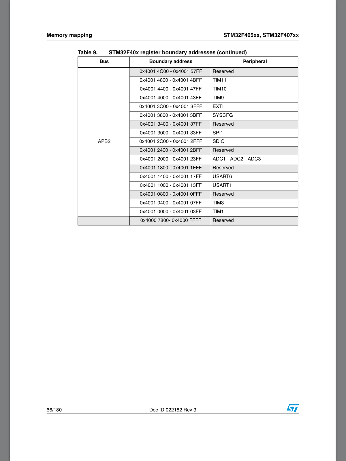
若你也把 Programming STM32 F2, F4 ARMs under Linux: A Tutorial from Scratch 裡頭的程式跑過一次, 就可體會整個開發流程了。上表就是這連結的內容。

g1.sh
1 file myur.elf
2 target remote localhost:1234
3 b getchar

這個 gdb script 可以減輕打字份量。

arm-none-eabi-gdb -x g1.sh

https://github.com/texane/stlink 的 readme 有些有用的資訊, 可瀏覽一下。

有個 free ide 可以參考:
http://www.coocox.org/index.html
原來 arm 除了 armcc 還有 arm gcc。
ref: https://launchpad.net/gcc-arm-embedded/+download

function reference:
STM32F10x Standard Peripherals Library

有了模擬器就不一定要把程式寫到版子上的 flash, flash 壽命有限, 減少讀寫次數不是壞主意。不過模擬器模擬的是 stm32-p103, 我使用的是 stm32f4 discovery, IO 部份可能有些不同, 僅能用來練習 arm coretex m 系列不含 IO 的程式, 而 qemu 似乎沒有模擬 svc, 我在測試有關 svc 的部份時, 都是使用真實開發板。若真要寫 stm32f4 開發版的程式, 最後還是得寫入 flash/ram 來測試, 只能在模擬器執行的程式, 那有什麼意思呢!

中文教學文件: http://wiki.csie.ncku.edu.tw/embedded/2012w7

恭喜! 看完這些文件和打造工作環境就去了半條命了吧!在 linux 下打造這些環境就要花上不少時間。如果你用 MDK5 就不用管這些事情, install MDK5 就可以了。

而真正的困難現在才剛開始, 先來練習模擬器上的程式, 不需要 st-link, openocd。

簡單的版本很簡單, 難的版本很難, 跟著 http://wiki.csie.ncku.edu.tw/embedded/Lab1 把 main.c compile 起來吧!

文件中的模擬器在這裡 https://github.com/beckus/qemu_stm32, 可自行更新。

qemu_stm32 編譯方式
apt-get install libglib2.0-dev libpixman-1-dev libfdt-dev libsdl1.2-dev
git clone https://github.com/beckus/qemu_stm32.git
./configure --disable-werror --enable-debug \
--target-list="arm-softmmu" \
--extra-cflags=-DDEBUG_CLKTREE \
--extra-cflags=-DDEBUG_STM32_RCC \
--extra-cflags=-DDEBUG_STM32_UART \
--extra-cflags=-DSTM32_UART_NO_BAUD_DELAY \
--extra-cflags=-DSTM32_UART_ENABLE_OVERRUN
  

main.c
 1 #define USE_STDPERIPH_DRIVER
 2 #include "stm32f10x.h"
 3 #include "stm32_p103.h"
 4
 5 void busyLoop(uint32_t delay )
 6 {
 7   while(delay) delay--;
 8 }
 9
10 int main(void)
11 {
12     init_led();
13
14     while(1) {
15        GPIOC->BRR = 0x00001000;
16        busyLoop(500000);
17        GPIOC->BSRR = 0x00001000;
18        busyLoop(500000);
19     }
20 }

這個簡單的程式隱藏了很多很多的細節, 會讓我們誤以為寫個 mcu 程式很簡單, 塞個 main 在裡頭就可以了。使用廠商給的 library 來開發有點像在 os 下寫應用程式, 也不是壞事, 只不過這標題是作業系統之前的程式, 自然不用這樣的開發方式, 得把隱藏在 library 下的秘密挖出來, 不過光是打造開發環境就很辛苦了, 先讓自己輕鬆一下。

這支程式不能在 stm32f4 - discovery 正確執行, 別浪費時間寫到 flash 中, 在模擬器練習即可, 這是暖身用的。

用這樣的方式來啟動 qemu stm32 模擬器

qemu_stm32/arm-softmmu/qemu-system-arm -M stm32-p103 -kernel mymain.bin -S -gdb tcp::1234
qemu-system-arm -M lm3s6965evb -kernel list.bin -S -gdb tcp::1234

紅色的部份不加入, 就是直接執行 mymain.bin, 沒有 debug 功能。

開啟另外一個終端機:
arm-none-eabi-gdb
 1 descent@descent-u:cpp$ arm-none-eabi-gdb mycpp11.elf 
 2 GNU gdb (32-bit ARM EABI Toolchain JBS-2013.05-23-v2013.05-1-gd66a29f) 7.4.50.20120716-cvs
 3 Copyright (C) 2012 Free Software Foundation, Inc.
 4 License GPLv3+: GNU GPL version 3 or later <http://gnu.org/licenses/gpl.html>
 5 This is free software: you are free to change and redistribute it.
 6 There is NO WARRANTY, to the extent permitted by law.  Type "show copying"
 7 and "show warranty" for details.
 8 This GDB was configured as "--host=x86_64-unknown-linux-gnu --target=arm-none-eabi".
 9 For bug reporting instructions, please see:
10 <https://github.com/jsnyder/arm-eabi-toolchain>...
11 Reading symbols from /home/descent/my-git/jserv-course/stm32f4_prog/cpp/mycpp11.elf...done.
12 (gdb) l
13 1       #include "stm32.h"
14 2       
15 3       
16 4       int print(int i)
17 5       {
18 6         i+=1;
19 7       }
20 8       
21 9       int print(char c)
22 10      {
23 (gdb) target remote :1234
24 Remote debugging using :1234
25 ResetISR () at stm32.h:21
26 21      {
27 (gdb) b mymain
28 Breakpoint 1 at 0x18e: file mycpp11.cpp, line 23.
29 (gdb) c
30 Continuing.
31 
32 Breakpoint 1, mymain () at mycpp11.cpp:23
33 23        constexpr int d=1;
34 (gdb) n
35 24        int x=3;
36 (gdb) n
37 25        int y=9;
38 (gdb) n
39 27        char path[]=R"(/usr/local/aaa)";
40 (gdb) n
41 28        char wpath[]=R"("\usr\local\aaa")";
42 (gdb) n
43 30        int total = lambda_test(x, y);
44 (gdb) n
45 31        print(35);
46 (gdb) n
47 32        print('A');
48 (gdb) n
49 33        int arr[]={1,2,3,4,5};
50 (gdb) n
51 34        for (int &e : arr)
52 (gdb) n
53 36          print(e);
54 (gdb) n
55 34        for (int &e : arr)
56 (gdb) n
57 36          print(e);
58 (gdb) p e
59 $1 = (int &) @0x2000008c: 2
60 (gdb) display e
61 1: e = (int &) @0x2000008c: 2
62 (gdb) n
63 34        for (int &e : arr)
64 1: e = (int &) @0x2000008c: 2
65 (gdb) n
66 36          print(e);
67 1: e = (int &) @0x20000090: 3
68 (gdb) n
69 34        for (int &e : arr)
70 1: e = (int &) @0x20000090: 3
71 (gdb) n
72 36          print(e);
73 1: e = (int &) @0x20000094: 4
74 (gdb) n
75 34        for (int &e : arr)
76 1: e = (int &) @0x20000094: 4
77 (gdb) n
78 36          print(e);
79 1: e = (int &) @0x20000098: 5
80 (gdb) n
81 34        for (int &e : arr)
82 1: e = (int &) @0x20000098: 5
83 (gdb) n
84 38        while(1);
85 (gdb) quit
86 A debugging session is active.
87 
88         Inferior 1 [Remote target] will be killed.
89 
90 Quit anyway? (y or n) y

這樣就像是在 x86-pc/linux 下使用 gdb。

lm3s6965evb 是 ti 的版子, 官方 qemu 即內建, 不用另外找 patch, 在我測試 cm3 和週邊無關的程式碼時, 相當方便。
ref:
http://www.techtraining.eng.br/files/uploads/2013/04/18/lm3s6965-evm.pdf

openocd load file to memory:
> load_image  /home/descent/git/jserv-course/stm32_prog/factorial.bin 0x20000000
24 bytes written at address 0x20000000
downloaded 24 bytes in 0.008389s (2.794 KiB/s)
> mdb 0x20000000 24
0x20000000: 00 08 00 20 09 00 00 00 0a 20 00 21 09 18 01 38 7f f4 fc af ff f7 fe bf 

這樣就可以不用寫到 flash, 直接 load 到 sram 測試。
ref: http://openocd.sourceforge.net/doc/html/General-Commands.html

openocd 似乎有些問題, 若遇到奇怪的問題可使用 st-util 配合 gdb 來 debug, 也有可能需要重新開機。
arm-none-eabi-gdb
target remote localhost:4242

也可以指定 gdb port
root@w-linux:descent# st-util -p 1234
arm-none-eabi-gdb
target remote localhost:1234

toolchain 比一比
18M stlink/
descent@w-linux:jserv-course$ du -sh openocd
88M openocd
descent@w-linux:jserv-course$ du -sh /usr/local/csl/
130M /usr/local/csl/

-rwxr-xr-x 1 descent descent 510M 2013-04-15 15:07 mdk470a.exe

blackmagic (類似 openocd, st-util 的 tool):
https://github.com/blacksphere/blackmagic/wiki
http://embdev.net/articles/STM_Discovery_as_Black_Magic_Probe

STM32Cube (新版的 library): http://www.st.com/web/catalog/tools/FM147/CL1794/SC961/SS1743/LN1897

ref:
  1. http://wiki.csie.ncku.edu.tw/embedded/2012w7
  2. http://wiki.csie.ncku.edu.tw/embedded/Lab6
  3. HowTo_ToolChain_STM32_Ubuntu
  4. http://cms.mcuapps.com/techinfo/emulators/st-link/
  5. http://forum.ubuntu.org.cn/viewtopic.php?t=384021&p=2839453
  6. http://www.amobbs.com/forum-3020-1.html
  7. STM32 的 BOOT 概述
  8. Flashing programs to STM32. Embedded Bootloader
  9. Getting Started with the STM32F4 and GCC
  10. STM32 BOOT 位理解及设置
  11. Programming STM32 F2, F4 ARMs under Linux: A Tutorial from Scratch
  12. http://www.waveshare.net/shop/STM32F4DISCOVERY.htm
  13. STM32 笔记(七)IAR 平台,在内存中调试 STM32
  14. ARM9 2410 移植之在 Linux 下, 用 OpenJTAG+OpenOCD 燒寫 NAND Flash
  15. x86 版的 Arduino 來了,Intel Galileo 開發板的體驗、分析和應用
  16. STM32F4 DISCOVERY入手——功耗大解密
  17. book: Eclipse,OpenOCD,OpenJTAGv3.3 嵌入式开发教程